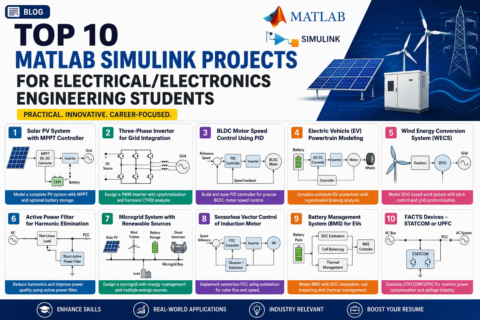
Why Simulation Projects Carry Weight in Electrical Engineering
Hardware prototypes often stall over blown MOSFETs, delayed PCB shipments, or lack of lab access. A rigorous Simulink model avoids those procurement delays while letting you test transient faults, thermal stress, and corner cases that would destroy physical bench setups.
Examiners evaluate simulation projects on the depth of the physical modeling, proper solver configuration, and whether the control loops handle realistic non-linearities. Below are 15 project ideas across power systems, renewables, motor drives, and vehicle electrification, along with the specific blocks and data you need to document them.
1. Solar PV System with Dynamic MPPT Control
Build a grid-connected or standalone photovoltaic array using the Simscape Electrical PV Array block. Implement and compare two Maximum Power Point Tracking algorithms: classical Perturb & Observe (P&O) and Incremental Conductance.
- Key Blocks: PV Array, Boost Converter, PWM Generator, Variable Irradiance Source.
- What to Measure: Settling time under rapid irradiance changes (e.g., 1000 W/m² to 400 W/m²) and tracking efficiency around the knee point.
- Technical Addition: Model partial shading with bypass diodes to examine multiple local maxima on the P-V curve.
2. Three-Phase Grid-Tied Inverter with LCL Filter
Design a three-phase voltage source inverter (VSI) that feeds power from a DC source into a 415V/50Hz utility grid. Regulate active and reactive power independently using synchronous reference frame (d-q frame) current controllers.
- Key Blocks: Universal Bridge, PLL (Three-Phase), Clarke/Park Transformation, LCL Filter.
- What to Measure: Run an FFT analysis in the Powergui block to verify that Total Harmonic Distortion (THD) stays under the 5% threshold defined by IEEE 519.
3. Closed-Loop BLDC Motor Speed Control with Hall Sensors
Model a Brushless DC motor driven by a six-step inverter (trapezoidal commutation) decoded from three Hall effect sensors. Use an inner current control loop and an outer PI speed loop.
- Key Blocks: Permanent Magnet Synchronous Machine (set to trapezoidal), Gates Logic Subsystem, Controlled Voltage Source.
- What to Measure: Torque ripple during phase commutations and speed recovery time following an abrupt mechanical load step.
4. Full EV Powertrain and Regenerative Braking Model
Simulate the electrical and longitudinal mechanical dynamics of an electric vehicle. Couple a battery pack and bidirectional DC-DC converter to an electric drive, then subject it to a standard drive cycle such as the FTP-75 or WLTP.
- Key Blocks: Battery (Lithium-Ion), Longitudinal Driver, Vehicle Body, Induction Motor / PMSM Drive.
- What to Measure: Energy regenerated into the battery during braking phases and state of charge (SOC) consumption over the cycle.
5. DFIG-Based Wind Turbine with Pitch Angle Control
Model a Doubly Fed Induction Generator connected to a wind aerodynamic profile. Control the rotor-side converter for maximum power extraction and the grid-side converter for DC-bus voltage stabilization.
- Key Blocks: Asynchronous Machine, Wind Turbine Model, Pitch Angle Controller.
- What to Measure: Power output smoothing when wind speeds exceed rated velocity and pitch blades feather.
6. Shunt Active Power Filter (SAPF) for Harmonic Mitigation
Industrial facilities running variable frequency drives draw heavily distorted non-linear currents. A shunt active power filter measures load harmonics and injects counter-phase currents to clean the grid feeder.
- Key Blocks: Non-linear Diode Rectifier Load, Instantaneous p-q Theory Controller, Hysteresis Current Controller.
- What to Measure: Source current waveforms and THD before and after activating the active filter.
7. Hybrid AC/DC Microgrid with Energy Management
Integrate a solar array, a small wind turbine, and a battery bank tied to a common DC bus, connected to an AC grid through an interlinking converter. Include a supervisory state-flow chart that schedules power dispatch based on generation and load demand.
- Key Blocks: Simscape Electrical Sources, Stateflow Chart, Bidirectional Buck-Boost Converter.
- What to Measure: DC bus voltage stability during transition from grid-connected to islanded mode.
8. Sensorless Field-Oriented Control (FOC) of an Induction Motor
Eliminate physical shaft encoders by estimating rotor speed and flux angle through a sliding mode observer (SMO) or Model Reference Adaptive System (MRAS).
- Key Blocks: Three-Phase Asynchronous Machine, Space Vector PWM (SVPWM), Rotor Flux Observer.
- What to Measure: Speed estimation error at low RPM and transient tracking during reversing commands.
9. EV Battery Management System (BMS) with Passive Cell Balancing
Model a multi-cell battery module where individual cells have slight manufacturing mismatches in capacity and internal resistance. Build balancing logic that bleeds high-voltage cells through shunt resistors during charging.
- Key Blocks: Equivalent Circuit Battery Cells, Switch Blocks, Logic Comparators.
- What to Measure: Voltage divergence across four to eight cells over charge-discharge cycles with balancing enabled versus disabled.
10. STATCOM for Grid Voltage Regulation and Reactive Support
Simulate a Static Synchronous Compensator tied to a weak transmission line feeding an inductive load. The STATCOM supplies or absorbs reactive power dynamically to maintain terminal voltage.
- Key Blocks: Three-Phase Source, Transmission Line (PI Section), Voltage Measurement, VSC Subsystem.
- What to Measure: Bus voltage profile during sudden three-phase inductive load switching.
11. Dual-Source Renewable System with Shared DC Link
Combine a photovoltaic string and a small permanent-magnet wind generator feeding a central DC link. Regulate each source's converter independently while a central battery takes up power imbalances.
- Key Blocks: PMSG Wind Turbine, PV Array, DC-DC Converters, PI Voltage Regulators.
- What to Measure: Power balance between generation, battery storage, and dynamic residential load profiles.
12. Low-Voltage Residential DC Microgrid
Unlike standard AC domestic lines, DC distribution cuts out redundant AC-DC conversion steps for consumer electronics, heat pumps, and rooftop solar. Model a 48V or 380V residential DC bus feeding constant-power loads (CPLs).
- Key Blocks: Buck Converter, Battery Storage, Constant Power Load Blocks.
- What to Measure: DC voltage oscillations caused by the negative impedance characteristics of constant-power loads.
13. Power Transmission Line Fault Detection and Classification
Simulate single line-to-ground (LG), line-to-line (LL), and double line-to-ground (LLG) faults on a transmission line. Extract transient three-phase current signals and process them with discrete Wavelet Transform (DWT) to classify the fault type within a half-cycle.
- Key Blocks: Three-Phase Fault Block, Distributed Parameter Line, Discrete Wavelet Transform (MATLAB Function).
- What to Measure: Detection delay in milliseconds and classification reliability across varied fault inception angles.
14. Resonant Inductive Wireless Power Transfer (WPT)
Model loosely coupled transmitter and receiver coils separated by an air gap using Series-Series (SS) or Series-Parallel (SP) compensation networks. Study power transfer efficiency across varying misalignments.
- Key Blocks: High-Frequency H-Bridge Inverter (85 kHz), Mutual Inductance Block, Rectifier.
- What to Measure: Power transfer efficiency versus coupling coefficient (k) and frequency deviations.
15. Multi-Area Load Frequency Control (LFC) with Renewable Penetration
Model a two-area interconnected power system with thermal governors and reheat turbines. Introduce intermittent solar penetration to create frequency deviations, then tune an automatic generation controller (AGC) to stabilize tie-line power exchange.
- Key Blocks: Transfer Function Blocks, Area Control Error (ACE) Subsystem, Tie-Line Model.
- What to Measure: Frequency overshoot, settling time, and tie-line power oscillations after a sudden 0.1 p.u. load increase.
Practical Guidelines for Project Defense
- Avoid continuous solvers on switching circuits: Switching converters run slowly with standard
ode45. Use stiff solvers likeode23tbor discrete simulation with sample times between 1 µs and 10 µs. - Label your scope axes: Unlabeled scopes with generic signal lines look unfinished. Use the Scope Manager to add signal names, units (Volts, Amperes, Nm), and clear legends.
- Validate against equations: Include hand calculations for component sizing (inductor ripple formulas, capacitor hold-up values, filter cutoff frequencies) alongside your simulation output.
Related Verified MATLAB & Simulink Projects
Need pre-built, debugged Simulink models with complete parameter initialization scripts and documentation? Explore top related solutions:
Common Engineering Troubleshooting & Q&A
Frequently encountered bugs, solver convergence issues, and implementation questions answered by our engineering mentors:
Recommended Engineering Articles
Need Custom MATLAB / Simulink Implementation?
Our team of PhD engineers build custom simulation plants, train machine learning agents, tune PID/MPC controllers, and deliver complete, executable code with Turnitin reports.