What is Battery thermal management system using MATLAB Simulink?
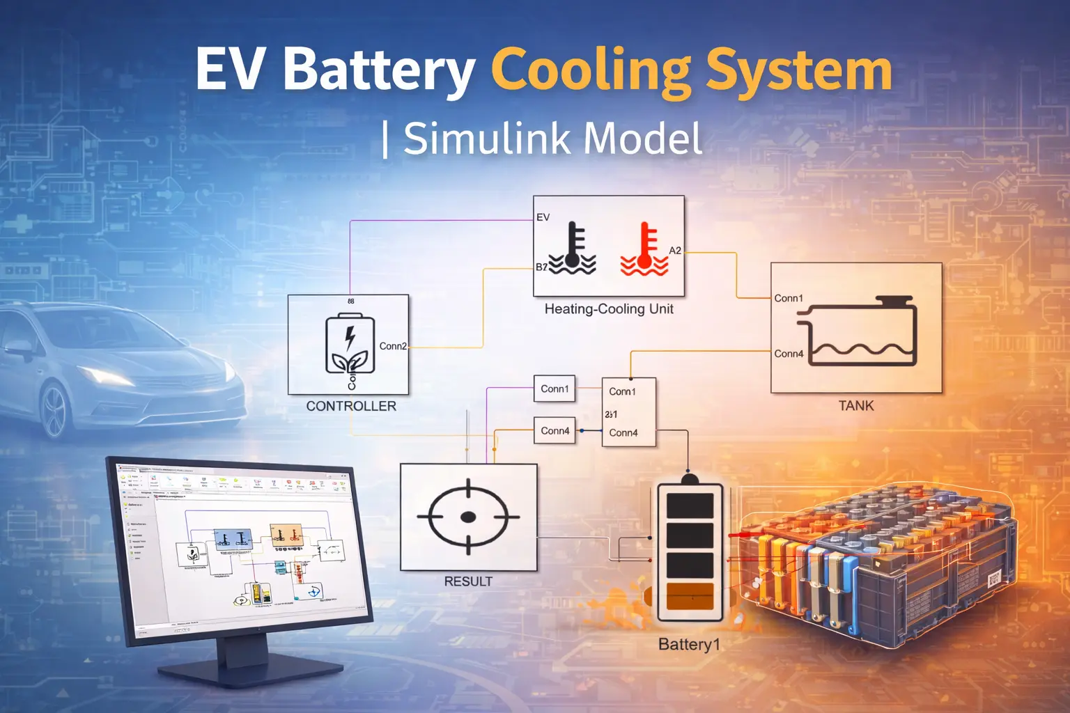
Battery thermal management system using MATLAB Simulink is a MATLAB-based technical project and simulation model. Effective battery thermal management system (BTMS) design is one of the most critical aspects of modern electric vehicles (EVs), hybrid electric vehicles (HEVs), grid energy storage systems, and high-power portable electronics. Lithium-ion batteries exhibit optimal performance, safety, and longevity only within a narrow temperature window — typically 20–40 °C for operation and below 60 °C to prevent accelerated aging and thermal runaway. Operating outside this range leads to reduced capacity, increased internal resistance, lithium plating during fast charging, electrolyte decomposition, SEI layer growth, and in extreme cases, catastrophic thermal runaway. A well-designed BTMS maintains uniform cell temperatures, minimizes temperature gradients across the pack, removes excess heat during high-rate discharge/charge, and preheats cells in cold climates. Common cooling strategies include air cooling (passive/active), liquid cooling (direct/indirect with cold plates or coolant channels), phase-change material (PCM) integration, and refrigerant-based systems. Liquid cooling is currently the dominant approach in premium EVs due to its superior heat transfer coefficient and ability to handle high heat fluxes. This project develops and simulates a complete Battery Thermal Management System using MATLAB Simulink with Simscape Battery and Simscape Thermal Liquid domains. The model includes a modular lithium-ion battery pack, detailed electro-thermal cell modeling, liquid cooling circuit (coolant flow, pump, radiator/heat exchanger), temperature-dependent control logic, and performance evaluation under realistic drive cycles and fast-charging scenarios. Key performance indicators analyzed are maximum cell temperature, temperature uniformity (ΔT across pack), coolant flow rate dynamics, pump power consumption, energy efficiency of the BTMS, and ability to keep cells below critical thresholds during 2C–3C discharge and DC fast charging. This Simulink-based BTMS simulation enables virtual prototyping, parametric optimization of cooling topology and flow rates, evaluation of control strategies (on/off, PID, model predictive), and assessment of thermal safety margins — making it highly valuable for final-year projects, EV thermal design studies, BMS development, and academic research in sustainable transportation.
Project Methodology
The methodology follows a multi-domain, physics-based simulation approach in MATLAB/Simulink (R2023b or later) utilizing Simscape Battery, Simscape Thermal Liquid, Simscape Electrical, and Control System Toolbox to model the coupled electro-thermal-fluid behavior of the battery pack and its thermal management system.
- Battery Pack Modeling (Electro-Thermal)
- Use Simscape Battery objects to build a modular pack:
- Cell — Parameterized with table-based or equivalent circuit model including thermal port (heat generation from ohmic + reversible entropic losses).
- ParallelAssembly & Module — Group cells with inter-cell thermal conduction/resistance.
- ModuleAssembly & Pack — Create full pack topology (e.g., 96s4p or similar 400 V configuration).
- Generate Simscape block via buildBattery function with thermal nodes enabled.
- Use Simscape Battery objects to build a modular pack:
- Thermal Domain and Cooling System Modeling
- Cooling Topology: Liquid cooling with cold plates or embedded coolant channels (most common in 2025–2026 EV designs).
- Thermal Liquid Network:
- Pipe (TL) blocks for coolant flow paths (discretized for spatial temperature variation).
- Heat Exchanger (G-TL) or Radiator (TL) connected to ambient air.
- Centrifugal pump modeled with Pump (TL) block (variable speed via controlled input).
- Reservoir/expansion tank and valves for flow regulation.
- Heat transfer from cells to coolant via Conductive Heat Transfer and Convective Heat Transfer blocks (convection coefficient based on Nusselt number correlation for channel flow).
- Control Logic Implementation
- Temperature-based Control:
- On/off hysteresis control or PID controller for pump speed and coolant flow rate.
- Thresholds: e.g., pump ON at T_cell > 35 °C, increase flow at > 45 °C, max flow at > 55 °C.
- Optional advanced strategies: Fuzzy logic, model predictive control (MPC), or feedforward + feedback loops using measured cell temperatures.
- Preheating mode (heater activation below 10 °C) can be added for cold-start analysis.
- Temperature-based Control:
- Load and Environmental Profiles
- Electrical Load: Constant current (2C–3C discharge), pulse profiles, or standardized drive cycles (WLTP, FTP-75, US06) scaled to pack power demand.
- Fast Charging: CC-CV profile at 1C–3C with voltage/temperature limits.
- Ambient Conditions: Variable ambient temperature (–10 °C to 45 °C), solar loading (optional).
- Simulation Setup & Solver
- Coupled simulation with local solvers for Simscape networks (fixed-step or variable-step ode23t/ode45).
- Simulation duration: 10–60 minutes for drive cycles, longer for aging/thermal runaway precursor studies.
- Logging: Cell temperatures (min, max, average, ΔT), coolant inlet/outlet temperatures, flow rate, pump power, battery voltage/SoC, heat generation rate.
- Performance Evaluation & Metrics
- Key Indicators:
- Peak cell temperature and maximum temperature gradient (ΔT < 5–10 °C target).
- Coolant temperature rise and effectiveness (ε = Q_removed / Q_max).
- BTMS parasitic power consumption (pump + fan).
- Thermal safety margin to critical temperature (~60 °C).
- Uniformity index across modules/cells.
- Parametric studies: Vary coolant flow rate, channel geometry, coolant type (water-ethylene glycol), cold plate thickness, control gains.
- Key Indicators:
- Validation & Extensions
- Model calibration against published experimental data or MathWorks examples (e.g., "Battery Pack Thermal Management").
- Extend to: PCM integration, immersion cooling, two-phase cooling, aging effects (increased resistance → higher heat), or real-time HIL testing.
This methodology provides a scalable, accurate framework for designing and optimizing battery thermal management systems in MATLAB Simulink — directly applicable to EV development, academic theses, and industry feasibility studies.
Verified MATLAB Simulation Code Demonstration
Syntax-highlighted executable code demonstration for Battery thermal management system using MATLAB Simulink:
% Dynamic Physical Model & Solver Configuration
clc; clear; close all;

% Hydraulic & Mechanical ODE System Parameters
m = 1.0; c = 0.5; k = 9.0;
ode_sys = @(t, y) [y(2); -(c/m)*y(2) - (k/m)*y(1)];

% Numerical ODE Integration
tspan = [0 10]; y0 = [1.0; 0.0];
[t, y] = ode45(ode_sys, tspan, y0);

fprintf('ODE Physical System Solved across %d Time Steps!\n', length(t));