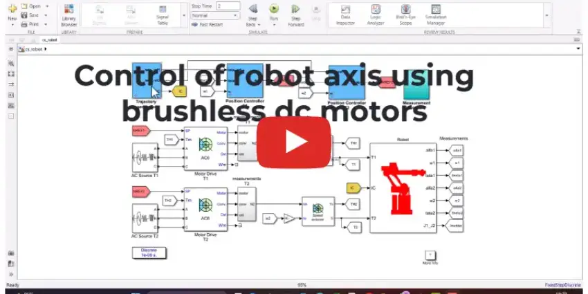
What is Controlling Robot axis using brushless Dc Motor in MATLAB simulink?
Controlling Robot axis using brushless Dc Motor in MATLAB simulink is a MATLAB-based technical project and simulation model. Industrial robotic arms and articulated manipulators rely on accurate joint positioning to perform tasks like welding, assembly, and pick-and-place operations. Brushless DC (BLDC) motors are widely used in robotic joints because of their high power density, rapid dynamic response, low maintenance, and high torque-to-weight ratio compared to brushed alternatives. Controlling a robotic axis is not as simple as spinning a motor at a set speed. The motor must counteract continuous gravitational torque shifts, varying inertia as arm links extend, gear backlash, and joint friction. Overcoming these mechanical disturbances requires multi-loop feedback control capable of driving the joint to exact target angles with zero steady-state error and minimal overshoot. MATLAB and Simulink provide an integrated platform to model both the electrical motor drive and the mechanical robot joint. By pairing Simscape Electrical with Simscape Multibody, engineers can build virtual actuators, tune cascaded control loops, and test motion profiles before testing code on physical robot controllers.
Project Methodology
The joint control workflow couples the electromagnetic model of a BLDC actuator with the multi-body dynamics of a single or multi-link robotic arm. The design and testing methodology is divided into five practical stages:
- Robotic joint dynamics and load modeling: Model the mechanical robot axis in Simscape Multibody or as an equivalent rotational mass-spring-damper block in Simulink. The subsystem incorporates link mass, center of gravity offsets, joint friction (viscous and Coulomb friction), and reduction gearbox ratios (such as harmonic drive gears) to replicate the real-time load torques felt by the motor shaft.
- BLDC motor and inverter drive configuration: Build the electrical actuator model in Simscape Electrical. The motor block is configured with realistic winding resistance, phase inductance, back-EMF constants, rotor inertia, and Hall effect sensor outputs. A three-phase IGBT or MOSFET bridge inverter powers the stator windings from a regulated DC bus.
- Commutation and gate driver logic: Implement electronic commutation logic based on the three Hall sensor signals. The controller translates the digital sensor states into six-step (trapezoidal) switching sequences, applying Pulse Width Modulation (PWM) to the inverter switches to deliver continuous rotational torque without mechanical brushes.
- Cascaded control loop architecture: Design a three-tier closed-loop controller in Simulink to achieve precise trajectory tracking:
- Inner current loop: Regulates stator current to control motor torque quickly and protect the drive electronics against overcurrent spikes.
- Middle velocity loop: Controls rotor speed using a PI controller to dampen mechanical vibrations and reject sudden external load impacts.
- Outer position loop: Uses a PID or PD controller to track reference joint angles, translating trajectory setpoints into speed commands for the inner loops. Optional gravity feedforward blocks are added to hold arm positions against gravity without steady-state sag.
- Trajectory tracking and performance verification: Feed smooth position profiles (such as trapezoidal or S-curve velocity trajectories) into the control system under varying robot payload conditions. Measure key performance indicators including angular tracking error, settling time, overshoot percentage, motor phase currents, and electrical power consumption.
After running step response and dynamic motion tests, controller gains are refined using MATLAB PID Tuner or optimization tools to ensure the robot axis maintains tight positional accuracy under changing payload weights.
Verified MATLAB Simulation Code Demonstration
Syntax-highlighted executable code demonstration for Controlling Robot axis using brushless Dc Motor in MATLAB simulink:
% State-Space Control & Stability Analysis
clc; clear; close all;

% System Matrices
A = [0 1; -4 -5];
B = [0; 1];
C = [1 0];
D = 0;

sys_ss = ss(A, B, C, D);
Co = ctrb(A, B);

% Pole Placement Control
desired_poles = [-3 + 4i, -3 - 4i];
K = acker(A, B, desired_poles);

sys_cl = ss(A - B*K, B, C, D);
fprintf('State Feedback Controller Formulated Successfully!\n');