
What is DC Motor Speed Control using Chopper & PI Controller in MATLAB Simulink?
DC Motor Speed Control using Chopper & PI Controller in MATLAB Simulink is a MATLAB-based technical project and simulation model. DC motors remain widely used in industrial automation, robotics, electric vehicles, conveyor systems, and traction applications due to their excellent speed-torque characteristics, simple control, and high starting torque. Precise speed control is essential to maintain performance under varying load conditions, supply voltage fluctuations, or disturbances. A chopper-controlled DC motor drive employs a DC-DC converter (typically a buck chopper) to vary the average armature voltage by adjusting the duty cycle via Pulse Width Modulation (PWM). This method provides smooth, efficient speed regulation below base speed with minimal power loss compared to resistive methods. To achieve accurate and stable speed tracking with zero steady-state error, a Proportional-Integral (PI) controller is integrated in the feedback loop. The PI controller processes the speed error (difference between reference and actual speed) to generate the duty cycle command, ensuring fast response, reduced overshoot, and robust disturbance rejection. This project develops and simulates a closed-loop chopper-fed DC motor speed control system in MATLAB Simulink using Simscape Electrical and Control System Toolbox. Key features include: separately excited or permanent magnet DC motor model, one-quadrant buck chopper, PWM generation, PI speed controller tuning, step response analysis, load torque disturbance rejection, and performance metrics like rise time, settling time, overshoot, and steady-state error. The simulation demonstrates effective speed regulation across reference changes and load variations — ideal for final-year engineering projects, control systems courses, and industrial drive design studies.
Introduction
DC motors remain widely used in industrial automation, robotics, electric vehicles, conveyor systems, and traction applications due to their excellent speed-torque characteristics, simple control, and high starting torque. Precise speed control is essential to maintain performance under varying load conditions, supply voltage fluctuations, or disturbances.
A chopper-controlled DC motor drive employs a DC-DC converter (typically a buck chopper) to vary the average armature voltage by adjusting the duty cycle via Pulse Width Modulation (PWM). This method provides smooth, efficient speed regulation below base speed with minimal power loss compared to resistive methods. To achieve accurate and stable speed tracking with zero steady-state error, a Proportional-Integral (PI) controller is integrated in the feedback loop. The PI controller processes the speed error (difference between reference and actual speed) to generate the duty cycle command, ensuring fast response, reduced overshoot, and robust disturbance rejection.
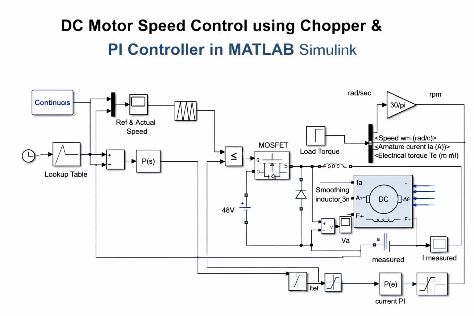
This project develops and simulates a closed-loop chopper-fed DC motor speed control system in MATLAB Simulink using Simscape Electrical and Control System Toolbox. Key features include: separately excited or permanent magnet DC motor model, one-quadrant buck chopper, PWM generation, PI speed controller tuning, step response analysis, load torque disturbance rejection, and performance metrics like rise time, settling time, overshoot, and steady-state error. The simulation demonstrates effective speed regulation across reference changes and load variations — ideal for final-year engineering projects, control systems courses, and industrial drive design studies.
Methodology
The methodology uses a simulation-based approach in MATLAB/Simulink (R2023b or later) combining Simscape Electrical for power electronics/motor modeling and Control System Toolbox for controller design.
- DC Motor Modeling
- Use the DC Motor block (Simscape Electrical) or parameterized equivalent circuit model.
- Key parameters: armature resistance (Ra), inductance (La), back-EMF constant (Ke), torque constant (Kt), moment of inertia (J), viscous friction (B), rated voltage/current/speed.
- Model includes mechanical load torque (TL) as disturbance input.
- Chopper (Buck Converter) Modeling
- Implement a one-quadrant buck chopper using MOSFET/IGBT switch + freewheeling diode + inductor + capacitor (or use Average-Value Chopper block for faster simulation).
- Input: fixed DC supply (e.g., 220 V).
- Output: variable average voltage to armature based on duty cycle (D = 0–1).
- PWM generation: Compare PI controller output (duty cycle reference) with a high-frequency sawtooth/triangular carrier (e.g., 1–10 kHz).
- PI Speed Controller Design
- Outer loop: Speed feedback from tachometer or derived from motor model (ω = dθ/dt).
- Error = Reference speed (ω_ref) – Actual speed (ω).
- PI controller: u = Kp × error + Ki × ∫error dt (output = duty cycle D).
- Tuning methods: Ziegler-Nichols, pole placement, or Simulink PID Tuner tool to achieve desired rise time, overshoot (<10–15%), and zero steady-state error.
- Optional: Anti-windup logic to prevent integrator saturation during large errors.
- Closed-Loop System Integration
- Connect PI output → PWM generator → Chopper switch gate.
- Feedback path: Actual motor speed → subtract from reference → PI input.
- Add step blocks for reference speed changes and load torque disturbances.
- Simulation Scenarios & Performance Evaluation
- Step response: Change reference speed (e.g., 500 → 1500 rpm).
- Load disturbance: Apply sudden torque change (e.g., 0 → 50% rated).
- Metrics: Rise time, settling time, peak overshoot, steady-state error, robustness to parameter variations (Ra, J).
- Use Scope, Dashboard blocks, and MATLAB plots for visualization (speed vs. time, duty cycle, armature current/voltage).
- Validation & Extensions
- Compare results with analytical transfer function (G(s) = K / (s(Js + B) + K²)) + PI controller.
- Extend to: Four-quadrant operation, fuzzy/ adaptive PI, sensorless control, or hardware-in-the-loop (HIL) testing.
This Simulink-based methodology enables rapid prototyping, controller tuning, and performance analysis of chopper-controlled DC motor drives with PI speed regulation.