
What is Control Speed of Induction Machine with Six-Step Method?
Control Speed of Induction Machine with Six-Step Method is a MATLAB-based technical project and simulation model. Induction motors dominate industry because they’re rugged, low-cost, and require minimal maintenance. Unlike DC motors, their speed cannot be controlled by voltage alone both voltage and frequency must vary together to maintain proper air-gap flux. If flux is too low, torque drops; if too high, saturation and overheating occur. Scalar control offers a simple open-loop solution. In six-step control (quasi-square wave inverter), a three-phase VSI generates stepped voltages with only six switching transitions per electrical cycle. The reference rotor speed is converted to stator frequency, and a constant V/f ratio is maintained to keep flux approximately constant. Each switch conducts for 120°, producing six-step line voltages that create a rotating magnetic field and torque. Six-step control is easy to implement, has lower switching losses, and provides about 15% higher fundamental voltage than sinusoidal PWM. However, it introduces more harmonics, causing torque ripple and current distortion. It’s a practical foundation before advanced methods like FOC or DTC.
Introduction
Induction motors dominate industry because they’re rugged, low-cost, and require minimal maintenance. Unlike DC motors, their speed cannot be controlled by voltage alone both voltage and frequency must vary together to maintain proper air-gap flux. If flux is too low, torque drops; if too high, saturation and overheating occur.
Scalar control offers a simple open-loop solution. In six-step control (quasi-square wave inverter), a three-phase VSI generates stepped voltages with only six switching transitions per electrical cycle. The reference rotor speed is converted to stator frequency, and a constant V/f ratio is maintained to keep flux approximately constant. Each switch conducts for 120°, producing six-step line voltages that create a rotating magnetic field and torque.
Six-step control is easy to implement, has lower switching losses, and provides about 15% higher fundamental voltage than sinusoidal PWM. However, it introduces more harmonics, causing torque ripple and current distortion. It’s a practical foundation before advanced methods like FOC or DTC.
Methodology
the example follows a classic open-loop V/f scalar control structure with six-step modulation. Here's a step-by-step explanation:
-
Reference Speed Input A desired rotor speed (ω_ref) is provided (e.g., via a step or ramp block in Simulink).
-
Slip Compensation (Basic Scalar Control) For accurate speed tracking, the stator frequency (f_s or ω_s) is set as: ω_s = ω_ref + ω_slip where ω_slip is a small compensation for load-dependent slip (often fixed or proportional to load in simple implementations). In pure open-loop V/f, slip compensation may be minimal or absent . the example uses a basic form where frequency is derived directly from reference speed, assuming small slip.
-
Constant V/f Ratio Generation The stator voltage magnitude (V_s) is proportional to frequency: V_s = k × f_s (k chosen so that at rated frequency, V_s = rated voltage). This keeps flux φ ≈ V_s / f_s constant below base speed. Above base speed, voltage is clamped at rated value (field weakening, though the example likely focuses on below-base operation).
-
Six-Step Inverter Operation A three-phase two-level VSI has six switches (IGBTs/MOSFETs with anti-parallel diodes). In six-step mode:
- Each switch conducts for 120° (one-third of the cycle).
- At any instant, exactly three switches are on (one per leg).
- The phase voltage is +V_dc/2 or -V_dc/2 relative to midpoint.
- Line-to-line voltage has six steps: ±V_dc, ±2V_dc/3, etc. The fundamental component is (2/π) × V_dc (about 1.1 × V_dc / √2 for RMS comparison to sine wave).
The controller generates six gate signals by dividing the electrical cycle into six 60° sectors and assigning switching states accordingly (e.g., using a lookup table or logic based on angle θ = ∫ ω_s dt).
-
Power Circuit in Simulink
- DC voltage source feeds the inverter (from Simscape Electrical).
- Three-phase inverter block connected to the stator of an Induction Machine Squirrel Cage block.
- Machine parameters: typical ratings like power, voltage, frequency, poles (e.g., 5 HP, 400 V, 50 Hz, 4 poles exact values from example).
- Mechanical load: often a constant or variable torque load.
-
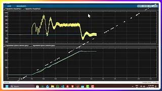
Simulation and Results The model simulates dynamic behavior:
- Apply step changes in speed reference.
- Observe acceleration/deceleration.
- Plot waveforms: stator voltages/currents (stepped), rotor speed, electromagnetic torque, slip.
- Results typically show: smooth speed tracking with some ripple due to harmonics, torque response with pulsations at 6× frequency.
This method is open-loop, so actual speed may deviate slightly under heavy load due to slip a key limitation students learn here.