
What is Grid-Connected Solar PV Powered EV Charging MATLAB Simulation?
Grid-Connected Solar PV Powered EV Charging MATLAB Simulation is a MATLAB-based technical project and simulation model. The rapid growth of electric vehicles (EVs) has significantly increased the demand for efficient, reliable, and sustainable charging infrastructure. Conventional EV charging stations primarily rely on grid electricity, which may increase peak load demand and carbon emissions when powered by fossil fuel–based sources. To address these challenges, integrating renewable energy sources—particularly solar photovoltaic (PV) systems—with EV charging stations has emerged as a promising solution. Solar PV–powered EV charging stations reduce dependency on the grid, lower operational costs, and minimize environmental impact. However, due to the intermittent nature of solar energy, grid integration becomes essential to ensure uninterrupted charging availability. A grid-connected solar PV EV charging station allows power exchange between the PV system, EV load, and the utility grid, ensuring system reliability and efficient energy management.
Introduction
The rapid growth of electric vehicles (EVs) has significantly increased the demand for efficient, reliable, and sustainable charging infrastructure. Conventional EV charging stations primarily rely on grid electricity, which may increase peak load demand and carbon emissions when powered by fossil fuel–based sources. To address these challenges, integrating renewable energy sources—particularly solar photovoltaic (PV) systems—with EV charging stations has emerged as a promising solution.
Solar PV–powered EV charging stations reduce dependency on the grid, lower operational costs, and minimize environmental impact. However, due to the intermittent nature of solar energy, grid integration becomes essential to ensure uninterrupted charging availability. A grid-connected solar PV EV charging station allows power exchange between the PV system, EV load, and the utility grid, ensuring system reliability and efficient energy management.
Methodology
The methodology adopted for the simulation of the grid-connected solar PV powered EV charging station consists of the following key steps:
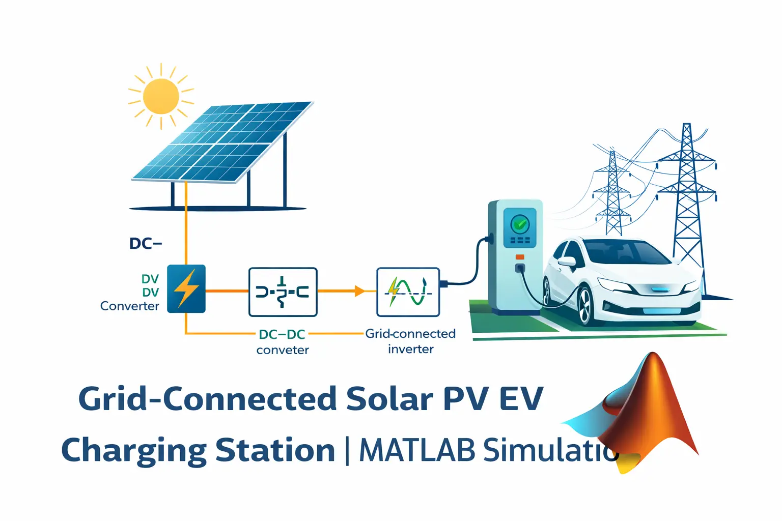
2.1 System Architecture Design
The overall system comprises:
-
Solar PV array
-
DC–DC converter with Maximum Power Point Tracking (MPPT)
-
DC link capacitor
-
Grid-connected inverter
-
Utility grid
-
EV battery and charging unit
The PV system serves as the primary energy source, while the grid acts as a backup and balancing source during insufficient solar generation.
2.2 Solar PV Modeling
A solar PV array is modeled using MATLAB/Simulink based on standard electrical characteristics such as:
-
Open-circuit voltage
-
Short-circuit current
-
Maximum power point (MPP)
The PV output varies with solar irradiance and temperature, which are provided as input parameters to study dynamic performance.
2.3 DC–DC Converter and MPPT Control
A DC–DC boost converter is employed to regulate the PV output voltage and extract maximum available power.
An MPPT algorithm (such as Perturb & Observe or Incremental Conductance) is implemented to ensure efficient PV power utilization under varying environmental conditions.
2.4 Grid-Connected Inverter Control
A voltage source inverter (VSI) connects the DC link to the utility grid.
The inverter control includes:
-
Phase-Locked Loop (PLL) for grid synchronization
-
Current control using PI controllers
-
Power flow management between PV, EV load, and grid
This ensures unity power factor operation and stable grid interaction.
2.5 EV Battery and Charging Model
The EV battery is modeled using a controlled current charging strategy.
Battery parameters include:
-
Rated capacity (Ah)
-
Nominal voltage
-
Initial State of Charge (SOC)
SOC variation is monitored during charging to analyze charging time and energy consumption.
2.6 Simulation and Performance Analysis
The complete system is simulated under different operating scenarios such as:
-
High and low solar irradiance
-
Variable EV charging demand
-
Grid-support and grid-export modes
Key performance metrics analyzed include:
-
Battery SOC progression
-
Charging current and voltage
-
Power sharing between PV and grid
-
System stability and efficiency
Verified MATLAB Simulation Code Demonstration
Syntax-highlighted executable code demonstration for Grid-Connected Solar PV Powered EV Charging MATLAB Simulation:
% Dynamic Physical Model & Solver Configuration
clc; clear; close all;

% Hydraulic & Mechanical ODE System Parameters
m = 1.0; c = 0.5; k = 9.0;
ode_sys = @(t, y) [y(2); -(c/m)*y(2) - (k/m)*y(1)];

% Numerical ODE Integration
tspan = [0 10]; y0 = [1.0; 0.0];
[t, y] = ode45(ode_sys, tspan, y0);

fprintf('ODE Physical System Solved across %d Time Steps!\n', length(t));