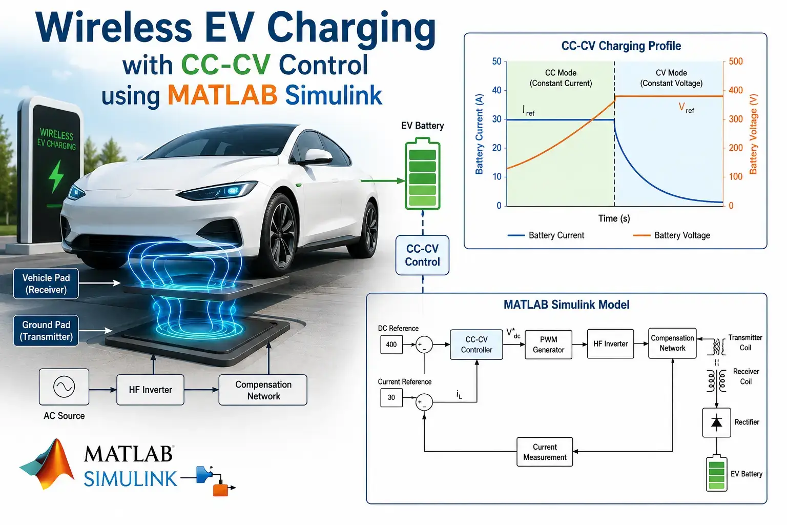
What is EV Charging in MATLAB Simulink with CC-CV Control using wireless?
EV Charging in MATLAB Simulink with CC-CV Control using wireless is a MATLAB-based technical project and simulation model. Wireless Electric Vehicle (EV) charging, also known as Wireless Power Transfer (WPT), is an emerging technology that enables convenient, contactless charging of EVs through electromagnetic induction. Unlike traditional plug-in chargers, wireless systems eliminate the need for physical connectors, improving user experience, safety, and reliability. One of the critical aspects of EV battery charging is the Constant Current - Constant Voltage (CC-CV) control strategy. In the CC phase, the charger delivers a constant current to quickly charge the battery up to a certain State of Charge (SOC). Once the battery voltage reaches a threshold, the system switches to the CV phase to prevent overcharging and maintain battery health. This blog explores the complete design and simulation of a Wireless EV Charging system with CC-CV control using MATLAB Simulink. The model integrates inductive power transfer coils, resonant compensation networks, power converters, and intelligent battery charging control making it highly relevant for researchers, students, and engineers working on EV technologies
Project Methodology
The proposed system is modeled and simulated in MATLAB Simulink using Simscape Electrical and Simulink blocks. Here’s the step-by-step methodology:
1. System Architecture
The overall system consists of the following main stages:
- Grid Side Converter (AC-DC Rectifier)
- High-Frequency Inverter (DC-AC, typically operating at 20–85 kHz)
- Transmitter Coil (Primary Pad)
- Resonant Compensation Network (Series-Series or LCC topology for better efficiency)
- Receiver Coil (Secondary Pad)
- Rectifier + DC-DC Converter (on vehicle side)
- Battery Management with CC-CV Controller
- EV Battery Pack
2. Wireless Power Transfer (WPT) Modeling
- Mutual inductance between transmitter and receiver coils is modeled with variable air gap and misalignment.
- Resonant capacitors are added on both primary and secondary sides to achieve resonance at the operating frequency.
- Power transfer efficiency is optimized by tuning coupling coefficient (k) and quality factor (Q).
3. CC-CV Control Strategy
- Constant Current (CC) Mode: A PI controller regulates the current to a reference value (e.g., 0.5C or 1C rate) until battery voltage reaches the maximum limit.
- Constant Voltage (CV) Mode: The controller switches to voltage regulation mode while current tapers off naturally.
- Mode switching is implemented using hysteresis or smooth transition logic to avoid instability.
4. Simulation Tools & Parameters
- MATLAB/Simulink (R2025a or R2026a recommended)
- Simscape Electrical library for power electronics
- Scope blocks for monitoring voltage, current, SOC, power, and efficiency
- Typical parameters: Input 230V/400V AC, Switching frequency 85 kHz (SAE J2954 standard), Air gap 150–250 mm, Battery 400V nominal
5. Performance Analysis
- Charging time and SOC curve
- Power transfer efficiency vs. air gap/misalignment
- Battery voltage & current waveforms during CC and CV phases
- THD analysis and electromagnetic compatibility observations
Verified MATLAB Simulation Code Demonstration
Syntax-highlighted executable code demonstration for EV Charging in MATLAB Simulink with CC-CV Control using wireless:
% State-Space Control & Stability Analysis
clc; clear; close all;

% System Matrices
A = [0 1; -4 -5];
B = [0; 1];
C = [1 0];
D = 0;

sys_ss = ss(A, B, C, D);
Co = ctrb(A, B);

% Pole Placement Control
desired_poles = [-3 + 4i, -3 - 4i];
K = acker(A, B, desired_poles);

sys_cl = ss(A - B*K, B, C, D);
fprintf('State Feedback Controller Formulated Successfully!\n');