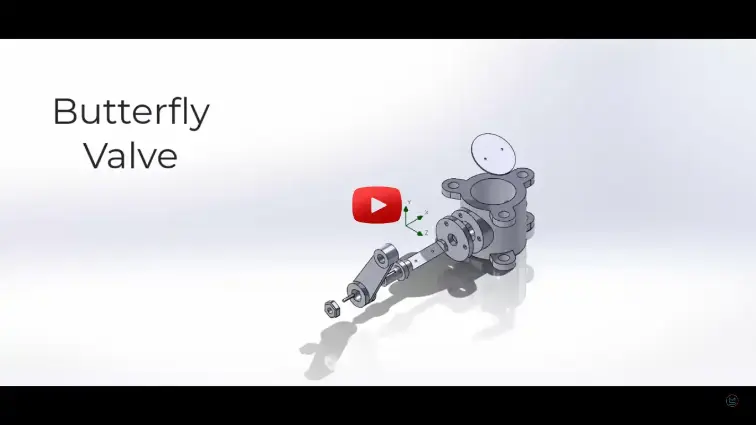
What is Designing of butterfly valve using Solidworks?
Designing of butterfly valve using Solidworks is a MATLAB-based technical project and simulation model. Butterfly valves are quarter-turn rotational flow control devices used in water treatment, chemical processing, oil and gas, and HVAC piping systems to throttle or isolate fluid streams. A complete industrial butterfly valve assembly includes a wafer or lugged valve body, a circular disc, a drive stem shaft, resilient elastomer or metal seals, gland bushings, and a top mounting flange compliant with the ISO 5211 actuator standard. Designing an efficient valve requires minimizing fluid flow resistance and pressure drop in the open position while maintaining bubble-tight shut-off sealing under maximum pipeline pressure. SOLIDWORKS provides parametric 3D CAD modeling, motion simulation, structural FEA, and integrated computational fluid dynamics (CFD) to design, assemble, and optimize valve components. This project covers the mathematical sizing, 3D part modeling, mechanical assembly, structural stress analysis, and internal flow simulation of an industrial butterfly valve.
Project Methodology
The design, assembly, and simulation of a butterfly valve in SOLIDWORKS follows a structured mechanical engineering workflow:
- Design Parameters & Valve Sizing: Define the nominal pipe diameter (e.g., DN100 / 4-inch), pipeline pressure rating (ANSI Class 150 or PN16), working fluid properties, allowable pressure drop, and required flow coefficient (Cv) based on industrial piping standards.
- Material Selection & Mechanical Properties: Assign materials in the SOLIDWORKS library, specifying Ductile Iron (ASTM A536) or Stainless Steel (CF8M/316) for the body and disc, high-tensile Stainless Steel (410/17-4 PH) for the stem, and EPDM or PTFE for the sealing liner.
- 3D Parametric CAD Part Modeling:
- Valve Body: Model the outer wafer or lugged casing with bolt centering lugs and ISO 5211 actuator mounting pads using Revolved Boss, Extruded Cut, and Chamfer tools.
- Valve Disc: Model the disc profile using hydrodynamic cross-sections to reduce flow separation and wake turbulence in throttled positions.
- Stem & Fasteners: Create the drive stem with keyed drive interfaces, O-ring sealing grooves, and precision disc locating pin holes.
- Resilient Seat & Bearings: Model the flexible EPDM/PTFE liner designed to provide interference sealing against the disc edge.
- Assembly & Kinematic Motion Constraints: Assemble all parts in the SOLIDWORKS Assembly workspace using concentric and coincident mates, applying Limit-Angle mates to restrict disc travel between 0° (fully closed) and 90° (fully open).
- Structural Finite Element Analysis (FEA): Using SOLIDWORKS Simulation, apply peak differential hydrostatic shut-off pressure across the closed disc face, constrain body bolt holes, apply maximum seating torque to the stem, and compute Von Mises stresses, displacement fields, and structural Factor of Safety (FOS).
- Internal Flow Simulation (CFD): Run fluid flow simulations in SOLIDWORKS Flow Simulation at various disc opening angles (15°, 30°, 45°, 60°, and 90°) to evaluate velocity contours, flow separation vortices, dynamic torque, and pressure drop curves.
- Manufacturing Documentation & BOM: Generate fully detailed 2D production drawings with standard tolerances, surface finish callouts for sealing faces, and an automated Bill of Materials (BOM).
Verified MATLAB Simulation Code Demonstration
Syntax-highlighted executable code demonstration for Designing of butterfly valve using Solidworks:
% MATLAB Constrained Numerical Optimization
clc; clear; close all;

obj_fun = @(x) (x(1)-2)^2 + (x(2)-3)^2;
x0 = [0, 0]; A = [1, 2]; b = 4; lb = [0, 0];

options = optimoptions('fmincon', 'Display', 'off', 'Algorithm', 'sqp');
[x_opt, fval] = fmincon(obj_fun, x0, A, b, [], [], lb, [], [], options);

fprintf('Optimization Solved: Minimum Value = %.4f\n', fval);