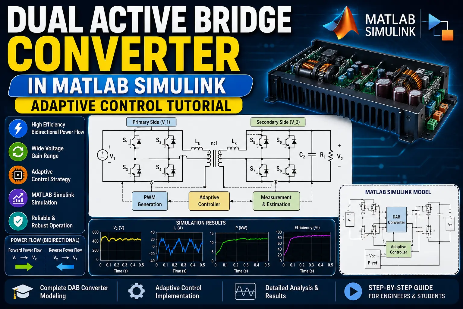
What is Dual Active Bridge Converter in MATLAB Simulink | Adaptive Control Tutorial?
Dual Active Bridge Converter in MATLAB Simulink | Adaptive Control Tutorial is a MATLAB-based technical project and simulation model. The Dual Active Bridge (DAB) converter is a high-frequency isolated bidirectional DC-DC converter widely used in applications such as electric vehicle charging, battery energy storage systems, renewable energy integration, and DC microgrids. Its ability to transfer power in both directions while providing galvanic isolation makes it an attractive solution for modern power-electronics systems. In this project, a Dual Active Bridge converter is modeled and simulated in MATLAB Simulink to analyze bidirectional power transfer and dynamic performance. The model consists of two active full bridges connected through a high-frequency transformer and leakage inductance. An adaptive control strategy is implemented to regulate the output voltage and control the transferred power under changing operating conditions.
Project Methodology
The DAB converter simulation is developed in MATLAB Simulink using the following methodology:
1. DAB Converter Configuration
A bidirectional DAB topology is constructed using two active full-bridge converters connected through a high-frequency transformer. The transformer provides electrical isolation and enables voltage matching between the two DC sides.
2. High-Frequency Transformer and Leakage Inductance
A high-frequency transformer is incorporated into the model along with leakage inductance. The leakage inductance plays an important role in controlling the power transferred between the primary and secondary bridges.
3. Active Bridge Switching
Both bridges are controlled using appropriate switching signals. Phase-shifted switching between the primary and secondary bridges is used to control the magnitude and direction of power transfer.
4. Bidirectional Power Flow
The converter is operated in both directions. In forward operation, power is transferred from the primary DC source to the secondary DC load. In reverse operation, power flows from the secondary side back toward the primary side.
5. Adaptive Control Implementation
An adaptive controller is integrated into the Simulink model to dynamically adjust the converter control signal according to system operating conditions. The controller responds to changes in reference voltage, load demand, and converter operating conditions.
6. PWM and Gate Signal Generation
The controller output is converted into appropriate gate pulses for the active-bridge switches. Proper synchronization and phase shifting of the gate signals are maintained to achieve the required power-transfer operation.
7. Measurement and Feedback
Voltage, current, power, and other converter variables are measured and fed back to the controller. The feedback signals are used to minimize the difference between the reference and actual output values.
8. Simulation and Performance Analysis
The complete DAB converter model is simulated under different operating conditions. Key parameters including output voltage, inductor current, transferred power, control response, and efficiency are analyzed to evaluate the performance of the proposed adaptive-control strategy.
Verified MATLAB Simulation Code Demonstration
Syntax-highlighted executable code demonstration for Dual Active Bridge Converter in MATLAB Simulink | Adaptive Control Tutorial:
% State-Space Control & Stability Analysis
clc; clear; close all;

% System Matrices
A = [0 1; -4 -5];
B = [0; 1];
C = [1 0];
D = 0;

sys_ss = ss(A, B, C, D);
Co = ctrb(A, B);

% Pole Placement Control
desired_poles = [-3 + 4i, -3 - 4i];
K = acker(A, B, desired_poles);

sys_cl = ss(A - B*K, B, C, D);
fprintf('State Feedback Controller Formulated Successfully!\n');