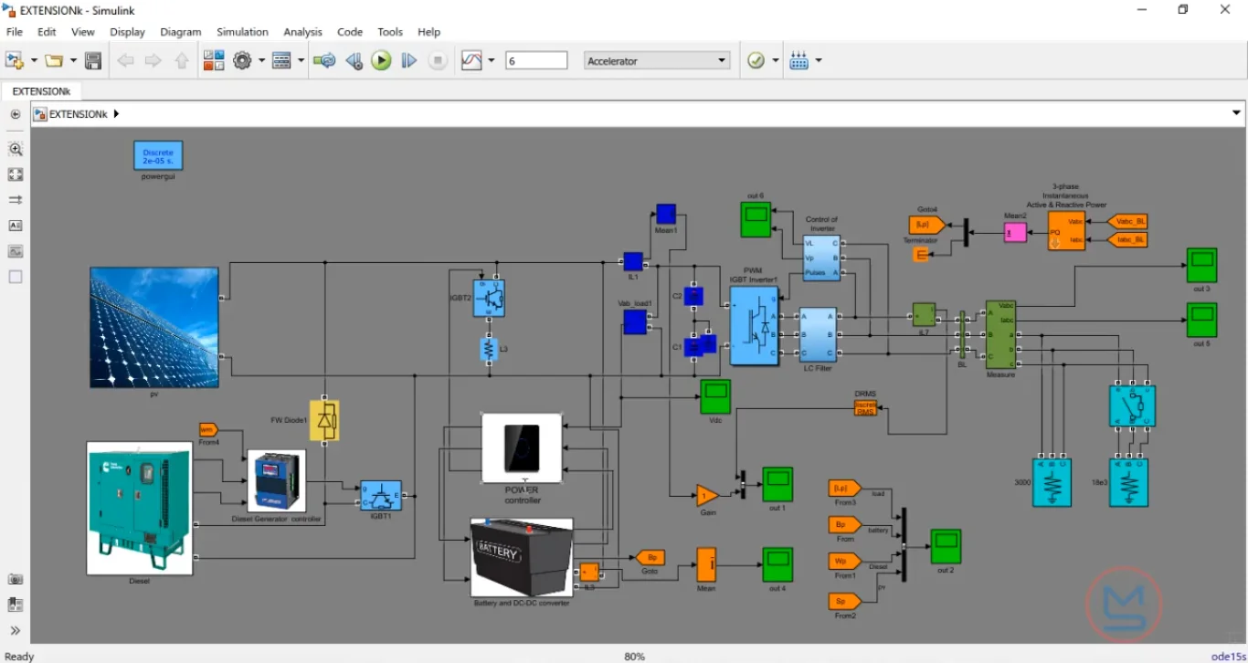
What is Grid-Connected PV-Diesel-Battery Energy Management System?
Grid-Connected PV-Diesel-Battery Energy Management System is a MATLAB-based technical project and simulation model. Hybrid energy microgrids combine renewable generation with conventional backup sources and energy storage. While solar photovoltaic (PV) arrays lower operating costs and emissions, their output fluctuates with solar irradiance and weather. Integrating battery energy storage systems (BESS) and diesel generators with the utility grid ensures continuous power supply, but coordinating multiple power sources requires active supervisory control. An Energy Management System (EMS) serves as the central decision-making layer for the hybrid microgrid. It continuously monitors grid power availability, electricity tariff rates, solar generation, and battery state of charge (SOC). The system then decides when to store surplus solar energy, when to export power to the main grid, when to discharge batteries during peak demand, and when to start the diesel generator during grid outages. Using MATLAB and Simulink (Simscape Electrical), engineers can model each generation and storage unit, design rule-based or optimization-driven dispatch logic, and verify system stability under varying load profiles and grid fault conditions.
Project Methodology
The system architecture combines solar PV arrays, a battery bank, a diesel generator, and the AC utility grid through power electronic converters governed by a centralized EMS logic controller. The development and testing methodology consists of five key stages:
- Microgrid component modeling: Model the primary power sources in MATLAB/Simulink using Simscape Electrical blocks. This includes the solar PV array with Perturb and Observe (P&O) maximum power point tracking (MPPT), a lithium-ion battery bank paired with a bidirectional DC-DC buck-boost converter, an emergency diesel generator with speed governor controls, and a three-phase utility grid interface.
- Power electronic converter and inverter integration: Connect DC sources to a common DC bus and use a voltage source inverter (VSI) to step up and synchronize the DC power with the 400V/230V AC distribution bus. Phase-locked loop (PLL) blocks ensure precise frequency and phase angle synchronization between the inverter and the utility grid.
- Energy management supervisory logic design: Build the supervisory control algorithm in Stateflow or Simulink. The controller operates on tiered priority rules: solar PV supplies local loads first, surplus solar charges the battery, and excess generation exports to the grid. If solar drops, the battery discharges to meet demand. If the grid fails and the battery SOC drops below a safe minimum threshold (typically 20% to 30%), the EMS automatically cranks the diesel generator.
- Peak shaving and economic dispatch configuration: Configure operating modes that respond to dynamic time-of-use electricity pricing. The EMS programs the battery to charge during low-tariff off-peak hours and discharge during high-rate peak periods to minimize grid power costs while keeping diesel fuel consumption low.
- Dynamic scenario simulation and performance testing: Subject the complete hybrid system to diverse 24-hour test cycles. These scenarios include rapid solar irradiance drops due to cloud cover, sudden factory or residential load steps, intentional grid disconnections (islanding mode), and automatic resynchronization back to the grid once power restores.
System performance is confirmed by tracking DC bus voltage regulation, AC bus frequency stability (maintaining 50 Hz or 60 Hz limits), total harmonic distortion (THD), and battery cycle efficiency under each operational state.
Verified MATLAB Simulation Code Demonstration
Syntax-highlighted executable code demonstration for Grid-Connected PV-Diesel-Battery Energy Management System:
% Spectral FFT Analysis & Signal Filtering
clc; clear; close all;

Fs = 1000; T = 1/Fs; L = 1500; t = (0:L-1)*T;
S = 0.7*sin(2*pi*50*t) + sin(2*pi*120*t);
X = S + 2*randn(size(t));

% Compute Fast Fourier Transform (FFT)
Y = fft(X);
P2 = abs(Y/L);
P1 = P2(1:L/2+1);
P1(2:end-1) = 2*P1(2:end-1);
f = Fs*(0:(L/2))/L;

fprintf('FFT Spectral Analysis Computed Successfully!\n');