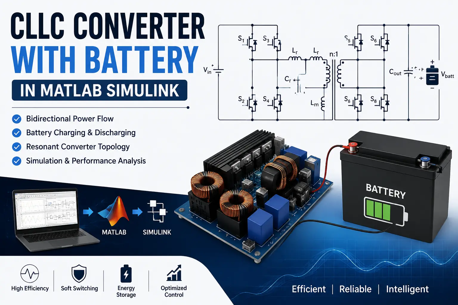
What is CLLC Converter with Battery in MATLAB Simulink | Modeling & Simulation?
CLLC Converter with Battery in MATLAB Simulink | Modeling & Simulation is a MATLAB-based technical project and simulation model. A CLLC resonant converter is an isolated DC-DC converter topology that can provide bidirectional power transfer between a DC bus and a battery energy-storage system. Its resonant network enables soft-switching operation, which can reduce switching losses and support high-frequency operation. These characteristics make bidirectional CLLC converters attractive for battery energy-storage and electric-vehicle charging applications. In this project, a CLLC converter with a battery is modeled and simulated in MATLAB Simulink to investigate battery charging and discharging operation. The model can be developed with a high-frequency full-bridge stage, CLLC resonant tank, high-frequency transformer, secondary-side bridge, DC-link/battery interface, and closed-loop controller. Frequency modulation is commonly used to regulate power flow through the resonant network
Project Methodology
Verified MATLAB Simulation Code Demonstration
Syntax-highlighted executable code demonstration for CLLC Converter with Battery in MATLAB Simulink | Modeling & Simulation:
% State-Space Control & Stability Analysis
clc; clear; close all;

% System Matrices
A = [0 1; -4 -5];
B = [0; 1];
C = [1 0];
D = 0;

sys_ss = ss(A, B, C, D);
Co = ctrb(A, B);

% Pole Placement Control
desired_poles = [-3 + 4i, -3 - 4i];
K = acker(A, B, desired_poles);

sys_cl = ss(A - B*K, B, C, D);
fprintf('State Feedback Controller Formulated Successfully!\n');