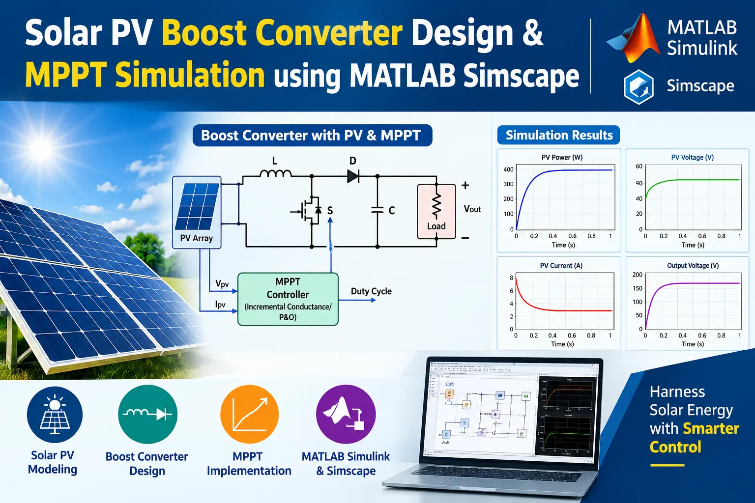
What is Solar PV System with MPPT Using Boost Converter Using MATLAB Simulink/Simscape?
Solar PV System with MPPT Using Boost Converter Using MATLAB Simulink/Simscape is a MATLAB-based technical project and simulation model. Solar panel output varies continuously with sunlight and temperature. Connecting an electrical load directly to the panels forces them away from their optimal operating voltage, leading to lost power. An intermediate boost DC-DC converter solves this by adjusting its switching duty cycle to keep the panels at their maximum power point. This design models a 2 kW solar setup in Simscape, demonstrating string sizing, MPPT tracking, and automatic voltage regulation during low-load conditions.
Project Methodology
1. Panel sizing and string arrangement
- Target capacity: 2.00 kW total output feeding into a 400 V DC bus.
- Minimum panels per string (8 panels / 1.80 kW): Keeps the panel voltage high enough so the converter does not need an extreme, inefficient duty cycle above 80%.
- Maximum panels per string (10 panels / 2.25 kW): Prevents panel open-circuit voltage from rising above the 400 V bus, which would cause uncontrolled current to bypass the switch through the diode.
- Selected setup: 1 string containing 9 panels in series, producing 2.03 kW under standard conditions.
- Fast simulation model: Instead of calculating separate diode equations for all 9 panels, the model combines them into an equivalent controlled source, speeding up simulations by about 85%.
2. MPPT algorithms
The model includes two selectable algorithms via a variant setting:
- Perturb and observe (
MPPT = 0):- Slightly nudges the panel voltage up or down.
- Checks if output power went up or down compared to the previous step.
- Keeps moving in the direction that increased power.
- Simple to build, but it constantly wobbles around the peak at steady state and can briefly step the wrong way during fast cloud cover changes.
- Incremental conductance (
MPPT = 1):- Compares how current changes relative to voltage changes.
- Knows mathematically when it has reached the top of the power curve.
- Stops adjusting once it hits the peak, eliminating the steady-state wobble and reacting faster to weather shifts.
3. Boost converter and dual-mode control
- Voltage step-up: Boosts panel voltage (around 270 V) up to the 400 V DC bus.
- MPPT mode: Active when the connected load or battery can take all the power the panels generate.
- De-rated voltage control mode: Activates when load power drops below solar output. Instead of pushing excess power and overcharging the 400 V bus, a PI controller steps the panels away from their peak, reducing generation to match the load.
4. PI controller tuning
- Boost converters naturally exhibit a temporary reverse response: when the switch duty cycle changes, output voltage momentarily dips before rising.
- The controller uses proportional gain and a phase-lead time constant to steady the loop.
- Proper tuning ensures the output voltage recovers quickly from load changes without ringing or tripping overvoltage protections.
Simulation output (MPPT mode)
Startup and tracking behavior
- Fast convergence: From zero power at startup, the system locks onto the maximum power point within 35 to 50 milliseconds.
- Operating values: The array settles at roughly 270 V and 7.5 A, delivering the expected 2.03 kW.
- Continuous current: Inductor current stays smooth and continuous throughout operation with small, well-filtered ripple.
- DC bus regulation: The output bus holds stable at 400 V with less than 0.5% voltage ripple.
Algorithm comparison
- Perturb and observe: Constantly steps back and forth across three operating points, causing about 12 W (0.6%) of power wobble at steady state.
- Incremental conductance: Stops stepping as soon as it reaches the peak, reducing power fluctuation to about 1.2 W and achieving 99.85% tracking efficiency.
- Sudden cloud response (1000 to 800 W/m²): Incremental conductance finds the new 1.62 kW operating point in 15 milliseconds without hesitation. Perturb and observe takes roughly 5 milliseconds longer due to an initial false step.
Verified MATLAB Simulation Code Demonstration
Syntax-highlighted executable code demonstration for Solar PV System with MPPT Using Boost Converter Using MATLAB Simulink/Simscape:
% State-Space Control & Stability Analysis
clc; clear; close all;

% System Matrices
A = [0 1; -4 -5];
B = [0; 1];
C = [1 0];
D = 0;

sys_ss = ss(A, B, C, D);
Co = ctrb(A, B);

% Pole Placement Control
desired_poles = [-3 + 4i, -3 - 4i];
K = acker(A, B, desired_poles);

sys_cl = ss(A - B*K, B, C, D);
fprintf('State Feedback Controller Formulated Successfully!\n');