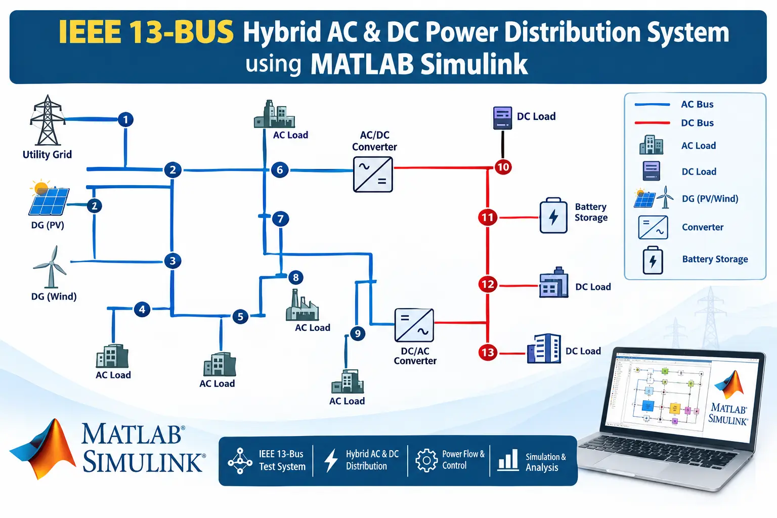
What is IEEE 13-BUS Hybrid AC & DC Power Distribution System using MATLAB Simulink?
IEEE 13-BUS Hybrid AC & DC Power Distribution System using MATLAB Simulink is a MATLAB-based technical project and simulation model. The global transition toward decentralized clean energy has fundamentally reshaped the architecture of modern power distribution networks. Traditional distribution grids were designed exclusively around alternating current (AC) principles, transmitting power unidirectionally from central generating stations down to passive consumer loads. However, the exponential proliferation of inherently direct current (DC) technologies—such as rooftop solar photovoltaics (PV), battery energy storage systems (BESS), electric vehicle (EV) ultra-fast DC charging hubs, and high-efficiency variable-frequency data centers—has exposed the efficiency bottlenecks of pure AC distribution.
Project Methodology
-
Hybrid Network Topology & Subgrid Modeling: The methodology begins by partitioning the distribution infrastructure into two coupled domains: an AC medium/low-voltage distribution feeder and a multi-terminal DC subgrid. The AC domain models traditional three-phase utility grid connections, primary distribution feeders, step-down distribution transformers, and AC-connected distributed generators such as wind turbines. Concurrently, the DC domain models medium- and low-voltage DC distribution lines connecting solar photovoltaic arrays, battery energy storage systems, EV fast-charging stations, and critical DC industrial loads.
-
AC Subgrid Power Balance Formulation: The AC network is formulated using standard nodal admittance techniques. Each AC node is categorized as a slack substation node, a voltage-controlled generator node, or a constant power load node. For every node, complex voltage magnitudes and phase angles are evaluated to establish active and reactive power balance. Line series resistances, inductive reactances, transformer leakage impedances, and shunt susceptances are integrated to compute power transfers and feeder voltage drops across all AC distribution branches.
-
Multi-Terminal DC Subgrid Power Transfer Formulation: The DC network operates without phase angles or reactive power, meaning power flow is dictated strictly by DC nodal voltage potentials and branch resistances. A dedicated DC conductance matrix is constructed to model the physical DC distribution feeders. Power flows between DC buses are computed directly from the potential differences between interconnected nodes, accounting for power injections from solar PV generation, battery storage charging/discharging states, and DC load demands.
-
Bidirectional Interlinking Converter (ILC) Operation & Control: The interlinking converter serves as the critical coupling bridge between the AC and DC subgrids. It is modeled to maintain instantaneous active power balance between both domains while accounting for internal conduction, semiconductor switching, and filter losses. The converter operates in flexible control modes: it can regulate the DC subgrid voltage at a specified reference while simultaneously injecting controlled reactive power into the AC feeder to bolster voltage profiles at weak distribution tail ends, or it can dispatch scheduled active power blocks between subgrids.
-
Unified Iterative Solution Framework: To achieve simultaneous convergence across both electrical domains, the methodology implements a unified iterative solver. Instead of solving AC and DC networks in isolated alternating loops, the system constructs an augmented sensitivity matrix that couples AC active and reactive power mismatches with DC active power mismatches. In each iteration, the algorithm calculates network-wide power imbalances, updates AC voltage magnitudes, AC phase angles, and DC bus voltages concurrently, and continues until all nodal mismatches fall below a strict convergence tolerance.
-
Benchmark IEEE 13-Bus Test System Integration: The methodology is applied to the standard IEEE 13-bus radial distribution feeder operating at medium voltage with an integrated low-voltage transformer branch. A five-bus multi-terminal DC microgrid is coupled at the heavily loaded tail end of the feeder via the interlinking converter. This benchmark setup allows direct evaluation of how renewable DC generation and battery storage can alleviate feeder overloading, reduce line losses, and restore drooping voltages along the entire AC radial line.
-
Simulink Model Architecture & Dynamic Verification: The final stage of the methodology involves building and simulating the entire hybrid system in MATLAB Simulink R2024a using Simscape Specialized Power Systems. The model features a modular orthogonal layout with dual DC distribution rails, color-coded functional subsystems, continuous powergui solvers, and real-time digital measurement displays. Dynamic time-domain simulation results are extracted and compared against the theoretical power flow results to verify steady-state accuracy, converter efficiency, and system loss distributions.
Verified MATLAB Simulation Code Demonstration
Syntax-highlighted executable code demonstration for IEEE 13-BUS Hybrid AC & DC Power Distribution System using MATLAB Simulink:
% Dynamic Physical Model & Solver Configuration
clc; clear; close all;

% Hydraulic & Mechanical ODE System Parameters
m = 1.0; c = 0.5; k = 9.0;
ode_sys = @(t, y) [y(2); -(c/m)*y(2) - (k/m)*y(1)];

% Numerical ODE Integration
tspan = [0 10]; y0 = [1.0; 0.0];
[t, y] = ode45(ode_sys, tspan, y0);

fprintf('ODE Physical System Solved across %d Time Steps!\n', length(t));