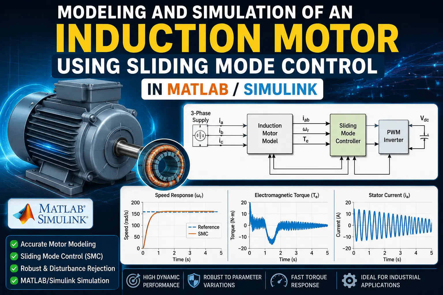
What is Modeling and Simulation of an Induction Motor Using Sliding Mode Control in MATLAB?
Modeling and Simulation of an Induction Motor Using Sliding Mode Control in MATLAB is a MATLAB-based technical project and simulation model. Three-phase induction motors (IMs) are the backbone of modern industrial automation, electric vehicles, and traction systems due to their high reliability, rugged construction, and cost-effectiveness. However, high-performance dynamic control of induction motors remains a complex control challenge. The induction motor is a highly coupled, multivariable, and nonlinear dynamic system with parameters (such as rotor resistance and load torque) that fluctuate significantly during operation. Traditional linear controllers, such as Proportional-Integral-Derivative (PID) controllers combined with Field-Oriented Control (FOC), often degrade in performance under parameter variations, load disturbances, and operating point shifts. To overcome these limitations, advanced nonlinear control strategies are required. Sliding Mode Control (SMC) is a Variable Structure Control (VSC) technique renowned for its strong robustness against external disturbances, rapid dynamic response, and invariance to matched system uncertainties. When applied to induction motor drives, SMC forces the system state trajectory onto a predefined sliding surface and maintains it along this manifold.
Project Methodology
- Dynamic modeling: The induction motor is converted into a rotating d-q reference frame aligned with the rotor flux. This separates the flux dynamics from torque production.
- Field-oriented control: Indirect Field-Oriented Control (IFOC) keeps rotor flux constant along the d-axis, allowing the q-axis stator current to regulate torque directly.
- Sliding surface design: An integral sliding surface is constructed from the speed tracking error and its accumulated integral over time to eliminate steady-state offset.
- Control law derivation: Using Lyapunov stability criteria, the controller calculates the reference q-axis current by combining an equivalent control term for nominal motor dynamics with a switching term to reject external disturbances.
- Chattering reduction: The discontinuous sign function is replaced with a smooth boundary-layer saturation function, preventing high-frequency torque ripple and shaft vibration.
- Simulink implementation: The simulation integrates the motor plant, rotor flux estimator, sliding mode speed block, inner current loops, and a space-vector PWM inverter.
- Performance testing: The system is tested under speed step changes, sudden load torque steps, and rotor resistance variations to confirm tracking speed and stability.
Verified MATLAB Simulation Code Demonstration
Syntax-highlighted executable code demonstration for Modeling and Simulation of an Induction Motor Using Sliding Mode Control in MATLAB:
% State-Space Control & Stability Analysis
clc; clear; close all;

% System Matrices
A = [0 1; -4 -5];
B = [0; 1];
C = [1 0];
D = 0;

sys_ss = ss(A, B, C, D);
Co = ctrb(A, B);

% Pole Placement Control
desired_poles = [-3 + 4i, -3 - 4i];
K = acker(A, B, desired_poles);

sys_cl = ss(A - B*K, B, C, D);
fprintf('State Feedback Controller Formulated Successfully!\n');