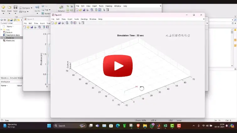
What is UAV Modeling & Control in Simulink | MATLAB Image Projects?
UAV Modeling & Control in Simulink | MATLAB Image Projects is a MATLAB-based technical project and simulation model. Unmanned Aerial Vehicles (UAVs) and multirotor drones are underactuated, non-linear dynamic systems that require closed-loop feedback controllers to achieve stable hover, trajectory tracking, and autonomous navigation. Combining 6-Degree-of-Freedom (6-DOF) flight dynamics with onboard image processing enables advanced capabilities, such as visual target tracking, object inspection, and precision landing on moving platforms. In MATLAB and Simulink, engineers can model rigid-body aerodynamics, configure cascaded attitude and position controllers, and simulate computer vision algorithms that extract spatial coordinates from live camera frames. This project covers the mathematical derivation of quadcopter dynamics, cascaded PID controller tuning, image segmentation and blob tracking in Computer Vision Toolbox, and closed-loop visual servoing flight simulations.
Project Methodology
The modeling, control system design, and vision-based tracking simulation of a UAV in MATLAB Simulink follows a structured aerospace and robotics workflow:
- 6-DOF Rigid-Body Dynamic Modeling: Formulate the non-linear Newton-Euler equations of motion in MATLAB to calculate translational accelerations (in the Earth inertial frame) and rotational dynamics (in the body-fixed frame) using mass, gravity, and the principal inertia tensor (Ixx, Iyy, Izz).
- Propulsion Aerodynamics & Motor Mixing: Model the relationship between rotor angular velocities and generated forces, using thrust (Kt) and drag (Kd) constants to construct the motor mixing matrix for an X-configuration quadcopter.
- Cascaded Flight Control Architecture:
- Outer Position Loop (10 Hz to 50 Hz): Tracks 3D navigational waypoints (X, Y, Z) and outputs commanded total thrust alongside reference roll (φ) and pitch (θ) angles.
- Inner Attitude Loop (100 Hz to 250 Hz): Regulates fast rotational angles and body angular rates using tuned PID controllers to ensure flight stability.
- Synthetic Sensor & Camera Feed Modeling: Simulate flight sensors, including an Inertial Measurement Unit (accelerometer and gyroscope), barometric altimeter, and a gimbaled onboard camera with adjustable resolution and frame rate.
- Image Processing & Target Detection: Process video frames using MATLAB Computer Vision Toolbox:
- Convert RGB frames into HSV color space for lighting-invariant target segmentation.
- Apply morphological opening and closing to remove image noise.
- Utilize
vision.BlobAnalysisto extract target centroids, bounding boxes, and pixel tracking error vectors.
- Visual Servoing & Trajectory Guidance: Design an Image-Based Visual Servoing (IBVS) routine that translates 2D pixel offset errors into real-time horizontal velocity commands, guiding the UAV position loop to center the target in the optical frame.
- Closed-Loop 3D Simulation & Error Analysis: Execute dynamic flight simulations in Simulink with 3D animation tools, evaluating trajectory tracking accuracy, attitude stability under crosswind disturbances, and visual target tracking latency.
Verified MATLAB Simulation Code Demonstration
Syntax-highlighted executable code demonstration for UAV Modeling & Control in Simulink | MATLAB Image Projects:
% MATLAB Image Processing & Edge Detection
clc; clear; close all;

% Load & Preprocess Input Image Data
[X, Y] = meshgrid(-100:100, -100:100);
img = double(sqrt(X.^2 + Y.^2) < 50);
img_noisy = imnoise(img, 'gaussian', 0, 0.01);

% Apply 2D Gaussian Denoising Filter
h = fspecial('gaussian', [5 5], 1.0);
img_filtered = imfilter(img_noisy, h);

% Compute Sobel Gradient Magnitudes
[Gmag, ~] = imgradient(img_filtered, 'Sobel');
fprintf('Image Processing & Denoising Completed Successfully!\n');