Question
PID tuning to meet conditions for settling time and overshoot while a stable system with minimum peak time and zero velocity error. So I am trying to find the gain values for a PI control system that would give me a settling time not exceeding 6 seconds, and an maximum overshoot not going over 5% while ensuring that the peaktime is the lowest it can be, and that the system is stable, and also has zero velocity error. I have written the following code. Starting with a kp and ki value of 1 each, I get a system that gives desirable overshoot and settling time, but I am wondering if the peaktime can be even lower while still having settling time <= 6 and overshoot <= 5. I am using the following toolboxes: Control System Toolbox Questions Using the rlocus function, I have also shown that the real parts of the poles are negative, so this demonstrates that my system is stable right? Also am I using Lsim correctly to determine if velocity error is zero? The resultant graph has a gray line showing the time response, and a blue line that is parallel to it. This means zero velocity error right? What is the best way to fine-tune the gain values kp and ki to minimize peak time while ensuring the above conditions are still met? I would like to use matlab only and no simulink for this please. clc clear all % plant transfer function G = tf([1], [0.5 1.5 1]) kp = 1 ki = 1 % PI controller C = tf([kp ki], [1 0]) % closed loop transfer function T = feedback(C*G, 1) rlocus(T) % Find the poles poles = pole(T) % step response figure; step(T); title('Step Response'); grid on; % Step analysis info = stepinfo(T) % Ramp Input t = 0:0.01:10; ramp = t; % System response to ramp figure; lsim(T, ramp, t); title('Ramp Response') legend grid on
Expert Answer

Prashant Kumar
PhD Expert
Answered Oct 6, 2026
Here is the solution using pidtune(). There is no direct way to input the desired settling time and overshoot percentage; however, you can enter the desired phase margin. This has been a concern for me in MATLAB for many years. Nevertheless, based on the desired overshoot percentage, you can apply the formula from your lecture notes to determine the desired phase margin.
%% The Plant
Gp  = tf([1], [0.5 1.5 1])
Gp =

           1
  -------------------
  0.5 s^2 + 1.5 s + 1

Continuous-time transfer function.
%% Using pidtune
Pm  = 68.2;     % desired Phase Margin
opt = pidtuneOptions('PhaseMargin', Pm, 'DesignFocus', 'balanced');
[Gc, info] = pidtune(Gp, 'pidf', opt)
Gc =

             1            s
  Kp + Ki * --- + Kd * --------
             s          Tf*s+1

  with Kp = 2.02, Ki = 1.87, Kd = 0.489, Tf = 0.00619

Continuous-time PIDF controller in parallel form.
info = struct with fields:
                Stable: 1
    CrossoverFrequency: 1.4142
           PhaseMargin: 72.6977
%% Closed-loop system
Gcl  = feedback(Gc*Gp, 1)
Gcl =

             81.01 s^2 + 328.2 s + 302.2
  -------------------------------------------------
  0.5 s^4 + 82.31 s^3 + 324.4 s^2 + 489.8 s + 302.2

Continuous-time transfer function.
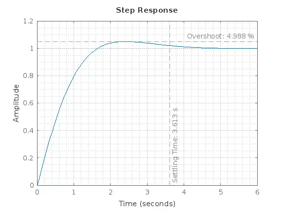
S = stepinfo(Gcl)
S = struct with fields:
         RiseTime: 1.1479
    TransientTime: 3.6131
     SettlingTime: 3.6131
      SettlingMin: 0.9088
      SettlingMax: 1.0499
        Overshoot: 4.9883
       Undershoot: 0
             Peak: 1.0499
         PeakTime: 2.3938
step(Gcl), grid on, grid minor
xline(S.SettlingTime,    '--', sprintf('Settling Time: %.3f s', S.SettlingTime), 'color', '#7F7F7F', 'LabelVerticalAlignment', 'bottom')
yline(1+S.Overshoot/100, '--', sprintf('Overshoot: %.3f %%',    S.Overshoot),    'color', '#7F7F7F', 'LabelVerticalAlignment', 'top')
100% Run Guarantee
3-Hour Fast-Track Delivery
Need a Custom Version or Complete Simulation for This Problem?
Our 500+ PhD engineers build, debug, and optimize working MATLAB scripts and Simulink (.slx) models tailored to your exact assignment rubrics with zero plagiarism.
Tested on MATLAB R2024b / R2026a
Turnitin 0% Plagiarism Report
Free 7-Day Revisions Guarantee
Have a different question? Ask here
Related pid tuning Questions & Solutions
Browse All →
Explore similar technical troubleshooting questions and verified MATLAB solutions:
Ready-to-Run MATLAB & Simulink Projects
Browse All Projects →