Question
Hi, I have a block diagram (included below) of a control system for a mass damped cart and a PID control system. I have set up the system and solved for the output (X position), but am now looking to solve for the actual voltage applied to the system and cannot figure out how to get that data from MATLAB. Additionally here is my code that I currently have: % Cart Transfer Function s = tf('s'); G = 1.5531/(s^2+10.0938*s); G.u = 'V'; %input (voltage) G.y = 'X'; % ouput (x position) % PID Controller Transfer Function H = pid(120,10,40); H.u = 'e'; % input (error) H.y = 'V'; % output (voltage) % Combined Transfer Function for R to X (X/R) Sum = sumblk('e = R - X'); % solve for error in terms of R and X XR = connect(H,G,Sum,'R','X'); % Solve for step response [x1, t1] = step(XR,1.5); My attempted solution was as follows: % Combined Transfer Function for R to V (V/R) VR = connect(H,G,Sum,'R','V'); % [V, t2] = step(VR,1.5); % Commented out because it throws error: % Error using DynamicSystem/step % Cannot simulate the time response of improper (non-casual) models. However this results in an improper model (More zeros than poles). I feel like there should be a function in MATLAB, but I have spent hours searching and nothing seems to fit what I am looking for. Any help is greatly appreciated, and let me know if there is anything I forgot or anything I can clarify.
Expert Answer

Prashant Kumar
PhD Expert
Answered Oct 22, 2026
AFACIT, you did everything correctly as far as defining and connecting the diagram. With the PID controller defined, the transfer function from R to V is, in fact, improper (the numerator is higher order than the denominator).
Consider using the fourth argument to pid. Instead of a pure derivative, the 'derivative' term will be of the form Kd*s/(Tf*s + 1), i.e., a high pass filter. Normally, one would select Tf as large as it can be while still meeting system response requirements. Making Tf large reduces the high frequency gain H(s) and reduces high frequency effects on the control due to changes in R or noise on the feedback signal. Alternatively, you can try to make it small to better approximate the pure derivative if that's what you want. I modified the code below to make Tf = 1e-3 as an example. Also, we can specify both V and X as outputs from connect so we only need one code to get both responses.
s = tf('s');
G = 1.5531/(s^2+10.0938*s);
G.u = 'V'; %input (voltage)
G.y = 'X'; % ouput (x position)
% PID Controller Transfer Function
H = pid(120,10,40,1e-3)
H =

             1            s
  Kp + Ki * --- + Kd * --------
             s          Tf*s+1

  with Kp = 120, Ki = 10, Kd = 40, Tf = 0.001

Continuous-time PIDF controller in parallel form.
H.u = 'e'; % input (error)
H.y = 'V'; % output (voltage)
% Combined Transfer Function for R to X (X/R)
Sum = sumblk('e = R - X'); % solve for e,rror in terms of R and X
%XR = connect(H,G,Sum,'R','X');
% Solve for step response
%[x1, t1] = step(XR,1.5);
% Combined Transfer Function for R to V  and X
clsys = connect(H,G,Sum,'R',{'V' 'X'});
zpk(clsys)
ans =

  From input "R" to output...
        40120 s (s+0.08579) (s+2.905) (s+10.09)
   V:  -----------------------------------------
       (s+0.08621) (s+2.584) (s+74.75) (s+932.7)

              62310 (s+2.905) (s+0.08579)
   X:  -----------------------------------------
       (s+0.08621) (s+2.584) (s+74.75) (s+932.7)

Continuous-time zero/pole/gain model.
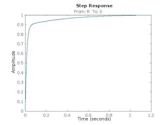
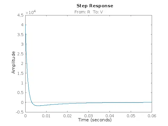
% call step twice because the X repsonse takes longer than the V response
figure
step(clsys('X','R'))
figure
step(clsys('V','R'))
100% Run Guarantee
3-Hour Fast-Track Delivery
Need a Custom Version or Complete Simulation for This Problem?
Our 500+ PhD engineers build, debug, and optimize working MATLAB scripts and Simulink (.slx) models tailored to your exact assignment rubrics with zero plagiarism.
Tested on MATLAB R2024b / R2026a
Turnitin 0% Plagiarism Report
Free 7-Day Revisions Guarantee
Have a different question? Ask here
Related block diagram Questions & Solutions
Browse All →
Explore similar technical troubleshooting questions and verified MATLAB solutions:
Ready-to-Run MATLAB & Simulink Projects
Browse All Projects →